3D CAD
Models, assemblies, drawings, and revision-controlled documentation.
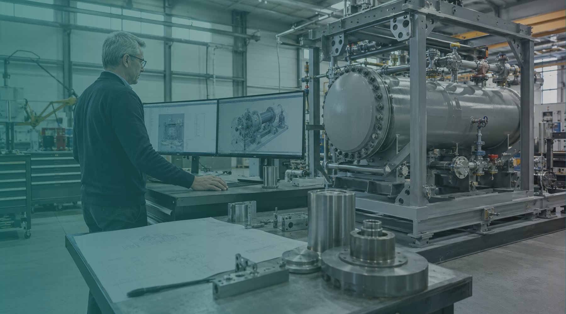
Mechanical design studio in Alberta
Mazi Inc. turns field constraints, worn parts, sketches, and equipment ideas into clear CAD models, fabrication drawings, and controlled design packages.
Models, assemblies, drawings, and revision-controlled documentation.
Practical design support for machinery, fixtures, weldments, and plant equipment.
Parts and assemblies recreated from samples, photos, measurements, or worn components.
Templates, iLogic, macros, BOM workflows, and repeatable drawing packages.

Mechanical design and documentation support delivered for Way-Tech Solutions Inc.
How Mazi works
Industrial teams do not need a lecture when a machine is down, a supplier drawing is missing, or a fabricator needs a cleaner package. They need someone who can understand the constraint, model the solution, document it properly, and keep the revision trail clean.
Igbo for the one who works with skill. It is the heritage Mazi Inc. was founded on and the standard every drawing package leaves under — read what that means.
Project work
CAD models and drawings prepared for review, fabrication, and controlled changes.
Layout and component changes focused on maintainability and smoother operation.
Parametric tools and drawing templates to reduce repetitive design effort.
Common questions
Mazi Inc. is a mechanical design engineering consultancy. We turn field constraints, worn parts, sketches and equipment ideas into 3D CAD models, fabrication-ready drawings, bills of material and controlled design packages. Core services are 3D CAD modelling and drafting, equipment and machinery design, reverse engineering, CAD automation, sheet metal and weldments, and pressure and piping support.
Mazi Inc. is based at 1138 Chinook Winds Circle SW, Airdrie, Alberta T4B 5S7. We serve Airdrie, Calgary, Edmonton, Red Deer, Fort McMurray and Lethbridge, and support clients remotely across Canada.
Yes. Reverse engineering is a core service. We recreate parts and assemblies from samples, photographs, field measurements or worn components where no drawings survive. Where a part is worn, we work back to what it was designed to be rather than measuring the wear, and any dimension we infer rather than measure is flagged on the drawing for you to confirm.
Autodesk Inventor, SolidWorks and NX for modelling; ANSYS and Altair OptiStruct for analysis; iLogic and VBA for automation. Deliverables are supplied in native CAD plus PDF, STEP and DWG so files are usable by your fabricators and internal teams without translation.
You do not need a finished brief. Photos, critical measurements, existing files such as PDF, DWG, STEP or STL, a worn component, or a description of what keeps failing is enough to scope the work. Telling us the decision or fabrication date the design must support helps most.
Six steps: intake to settle scope and timeline; concept development in sketches and early parametric models; detailed modelling of parts, assemblies and bills of material; analysis and verification covering stress, thermal and fit checks; review and revision at defined milestones; and delivery of an organised package of native CAD, PDFs and drawings. See the full process.
Start with the constraint
We will help define the right next deliverable: model, drawing, redesign, reverse engineering package, or automation workflow.